Thursday, January 5, 2012

The Tesla Valve

From Makezine.com: http://blog.makezine.com/archive/2012/01/the-tesla-valve-one-way-flow-with-no-moving-parts.html

The Tesla Valve is a one-way valve with no moving parts. Its geometry resists the flow of a fluid in one direction by redirecting some of it back at itself. I don't think it perfectly stops the fluid but it greatly resists it.


Shapeways user imperator made a printable version (with an unpictured cover) which he demonstrates in the video by blowing through it.


Putting tails on terrestrial/driving robots for stabilitation

From IEEE Spectrum: http://spectrum.ieee.org/automaton/robotics/diy/dinosaurlike-tails-make-terrestrial-mobile-robots-more-agile

This is a really clever idea that I'm surprised I've never seen before. Researchers from UC Berkeley put a tail on an RC car robot which moves up and down to stabilize it in the air as it goes off jumps and such. The tail simply turns to move the rest of the car body in the desired position as it flies through the air. Based on conservation of angular momentum, if the tail applies a torque within the tail-body system and moves one way, the body must counteract that and move in the other direction. They are using simple but interesting physics to their advantage. This is all based on how lizards and dinosaurs jump with their tails.


The video below is helpful. It shows the car dropped from an initially nose-down position and recovering to be level, as well as going over a steep bump.

Monday, December 26, 2011

Adafruit arcade buttons

For my alarm clock project I bought two translucent arcade buttons from Adafruit. Here's some things that I observed after I got them, especially on placing an LED inside. I couldn't really find any other examples or information about working with these, except this music keyboard project that Adafruit posted on their blog. They drilled LED-sized holes in the bottom and hot glued the LEDs in, but I didn't want to drill a hole.


Relative size. They look a little smaller here, but they are about medium size.

Side view

Bottom view

The tabs on the side hold the button in the hole that you drill for it. They compress and push out and there are multiple "steps" at the top depending on the thickness of the mounting material.

The inside. The top cover is pretty easily taken off by pushing in the snaps/tabs. The white part extends down to press on the switch on the bottom. It has a large white top surface, which makes the tops of the buttons look whitish and not see-though.

The white top part attached with no top cover.

Inside. There's a pretty good amount of room to mount lights, a little bit of circuitry, etc.

Here's a side view so you can see how much room there is. It's translucent, so you can see the center white post through the button and see how much room there is on the side of it.

The button, which is released by tabs in a similar way to the button top.

Putting an LED in. There is plenty enough room. I'm using an LED with long leads that can be bent around and through the side holes. It happened to be a tall, smooth LED with no rim on the bottom. It's green, sorry that it blends in with the blue switch.
I would suggest putting two in on each side of the switch, because the light gets diffused some by the white top, so it partially looks like a dot of color on one side. Putting two on each side would make it much better. The light goes through the button alright (like fiber optics), but again it would be better looking with two LEDs.

Side view of an undepressed button. The top is slightly convex, which is a little hard to see on camera, but easier in person. It's hard to feel, the top feels pretty flat. The datasheet also shows that it is convex. 

Depressed button.

Friday, December 9, 2011

Resource updates

I've reorganized my "resources." (This may not be important to any readers.)

I've redone the definition of a resource for myself so that I can manage them better. A resource is something from which I might get something to write about on this blog from. Now there's a list of main ones that I actually follow regularly, a list of other minor websites, and then posts on other things that aren't websites. I have made posts on some of the minor resources as I learn about them. I will update these first two resource posts as I get more. Some entries I have deleted or placed in the Other or simple Interesting Finds tag.

I've added another main resource that I won't do a post on. I have been following Adafruit Industries' blog for a while now.
Remember, even though I don't post extremely regularly, I do watch these resources and always save links in my bookmarks to good articles that I want to write on in the future.

My main, followed resources:
Makezine.com
Hack-a-day (hackaday.com)
Adafruit Industries' blog
IEEE Spectrum Automation blog

Link to main resources post
Link to minor resources post

Wednesday, November 30, 2011

Alarm clock project 1: initial opening and beginning research

This is the first post.
Second post: cutting
Third post: installing buttons and final look

My one complaint with my alarm clock is that the off button is very small. This is the button that turns the alarm off in the morning after it has gone to snooze a couple of times. So naturally you would want it to be big and accessible like the snooze button. But it's not. I thought it would be cool to modify the clock and add a big ol' mash-and-be-done button in its place and just solder the electrical connections to where the original button was. (Later I decided to throw on a bigger button for snooze while I'm at it).

Here's a bunch of the parts after it has been taken apart. The circuit board for the buttons was on the top, but you had to get to it from the bottom, so out comes everything in the way. Namely, the main "motherboard" and the CD player components.

And here's the rest of it! I still need the alarm clock, so I'm using the main circuit board while I'm working on this project. I have to use headphones and the clock's headphone jack since there's no speaker attached anymore. With the volume turned up they are loud enough to wake me up. The clock runs fine without the CD player attached. There's a transformer that takes the house current down to something reasonable, but it's still unnerving to handle a big messy open circuit that's plugged into the wall outlet...


Some inspirational parts:

On the CD player this gear is mounted by this unique piece of plastic (the curvy piece with three parts/arms). It's thin and designed to be flexible so that if the CD read head is driven too far and jams, this part shifts and flexes instead of breaking the gear.

This is how the radio tuner works. It shows which station you're on by this white, plastic-rubber piece. It curls up around the tuning wheel, to which it is attached. It curls and uncurls as you turn the wheel, moving right and left.

Here's a limit switch that has two flat, bendable contacts that are pressed together by a lever when the CD cover closes.
This is the opened position.

Closed position.

A similar switch on the CD player assembly. It's the black and clear plastic extending down from the circuit board in between the two motors. The two metal contacts are visible.
Open position.

Closed position.


Initial Project Pictures

Here is the front of the clock showing the size of the buttons. The button tops are a two plastic molds that press on small tactile switches.

Here is the power button area. I've drawn reference marks on scotch tape stuck on the clock. The paper is a stencil of the circuit board that goes underneath.
The shaded area with the X is the only area I can cut and put a button into. There is only a quarter of an inch of depth underneath that (the same size as the grid on the paper). This is not very big compared to what I had in mind, which was to cut away nearly all the available material underneath the power button and put a big ol' button there. Because of structural components that can't be cut away and the button circuit board's ribbon cable, that shaded part is all I have to work with.

I decided that's not enough and I'd have to find a different solution. There weren't any good buttons available that would be as big as that space but not very deep. I also didn't want an unsightly skinny or tall button. I began to think of other places were I could put a button and rout wires to it.
I realized that I could put a button right into the middle of the CD cover. I could leave out the CD player assembly and have lots of space to work with. I never listen to CDs on this clock anyway. Now that there's tons of room, I'm going to put another button for snooze.

I picked Adafruit's new arcade style buttons because they're cheap and look great. They're translucent and have room for an LED, so I might fit one inside and wire it to the button leads so that it lights up when pressed. Hopefully there will be the right kind of current to run the LED.
My other button option was this more boring one from Digi-key.

The total depth that extends down from underneath the button lip is 31.7 mm (from the details tab on the product page). It does not extend far enough to reach where the main circuit board is mounted. I've checked with the circuit board in place and there's tons of room for the button and routing the wire.

Here's another view. The short post is for mounting the CD player and the tall post is for mounting the main circuit board. The penciled line is the limit.

So now I will plan out the size of the buttons and where I'm going to mount them. Then when they come in I'll  inspect them more, cut the holes, mount them, solder them to wires and solder those to the contact points of the original buttons.

Friday, November 25, 2011

Taking apart a CD drive

A computer at home broke its CD drive, so after a new one was bought and installed, I nabbed the old one. I hoped to find interesting things inside and maybe I could use some parts for future projects. I'm researching and thinking about how I might use the moving frames as part of a plotter or something like that. The stepper motor and the moving frame for the CD read/write head could be pretty useful. Here are some pictures and descriptions.


All the main parts laid out, as viewed from the back of the drive (probably should have made them all face the camera :P ). The circuit boards are mounted underneath the cream-colored plastic frame, and the black CD tray slides into tracks on the top of the frame. I've taped the front cover of the drive to the tray for convenience and to keep track of it.


This next picture is the main mechanism for opening the the CD drive and sliding out the tray.

As you might expect, the tray is driven out by a rack and pinion. The driving pinion gear is the large black one in the upper corner. It is driven by a motor that normally pokes up through the curved, U-shaped space visible in the center (this drives the smaller black pulley with a rubber-band like belt).

The white plastic bar is instrumental for multiple things. When it is all the way to the left or right, the tray itself interacts with it and pushes it into the pinion gear, which moves it further. But then it gets moved out of the reach of both the pinion gear and the tray. It sits in one position or another (all the way right or left) until the tray moves the opposite way, interacts with it again, pushes it into the pinion gear, which moves it back the other way. More pictures of this later.


The CD read/write head and spinning motor frame is partially visible here (hereafter called the "rocker frame" for lack of a better name, because of the following description). This actually swings/falls down and away from the tray when it moves out. The front mechanism also involves this motion. When the white plastic bar moves sideways, it moves the rocker frame up and down. There are nubs in the frame that stick into the curved grooves in the white bar. These S-shaped grooves are also partially visible, since the rocker frame is in the down position.

If the CD drive jams, a paperclip can be poked through a hole in the front to open the tray. I've always wondered what it pushes inside. It goes through the square hole on the left and pushes the stubby, left-facing-L-shaped, white piece of plastic, which swings and pushes the white bar to the side by the straight bar it's a part of.

The small green circuit board is for burning LightScribe disks. They have tops that text or images can be burned into, I think with a laser.


A clearer overhead view of the front mechanism.


Here is a picture that includes a bottom view of the CD tray (as if it was flipped up). Here you can see the grooves that interact with the rest of the drive. This picture is annotated below.


The red parts interact with each other at later times than the blue parts. I'm not exactly sure when or in what way, exactly. But at the ends of the highlighted grooves in the tray there are angled parts that move the nubs on the white bar, so that's the basic idea.


A front view of the drive with one of the circuit boards laid into place. The previously mentioned piece of plastic that the paper clip pushes on is close to the hole now.


A view of the front mechanism circuit board. The center black square with the two buttons sticking up is used to see if the tray is fully in or out. See the next picture.


In the middle you can see those two buttons. They normally poke up farther through the cream-colored plastic frame if the circuit board was attached completely. The rectangular tabs on the white bar slide over the buttons and depress them in certain positions. The upper tab is close to one of these buttons in this picture.


A bottom view of the rocker frame, with the CD read/write head and spinning motor.


The rocker frame attaches to the main frame here with latches holding onto short axles for when it swings away from the CD tray.


The rocker frame taken out. Note the two black nubs mentioned earlier, now facing the bottom right corner of the picture. See the next picture.


Those nubs fit into these S-shaped grooves, also mentioned earlier.


A close up on the motor and screw gear that move the read/write head. I believe this motor is a stepper motor because it needs to be precise and because there are four electrical connections to it.


Here's a view of the read/write head. It's a precisely balanced laser with a lens. Notice the wires and silver metal blocks which appear to be magnets. I believe this is how the lens is precisely positioned.


Another view of the  lens.

Monday, September 12, 2011

Tubalcain machine shop Youtube videos

(Many of tubalcain's videos are posted on makezine.com, which is where I initially heard about them)

----------------
Here's a list of all his videos in order, including other series besides Machine Shop Tips!
However, I'm not sure if it's updated with his newest videos. I have looked through this list and now I get updated about new videos after subscribing to his channel on YouTube.
http://neme-s.org/Tubalcain/machine_shop_tips.htm
----------------


http://www.youtube.com/user/mrpete222

Tubalcain is a retired machine shop teacher that has many interesting how-to, tips, and teaching videos on Youtube. They are all excellent and he has many of them. His Machine Shop Tips series is well known.

Samples:

Sine bar (helps with machining angles):


Hole transferring (drilling a hole in an exact, corresponding place):

Dean Williams' mechanical engineering and machining site

(I think I was led to this from a post on makezine.com)

http://www.deansphotographica.com/machining/projects/projects.html

Dean Williams' site has many projects that he has done with his metalworking machines, such as lathes and CNCs. He makes many of his own tools for machining and cutting in unique ways. I wish I new more about the kinds of things he does.

Some samples:

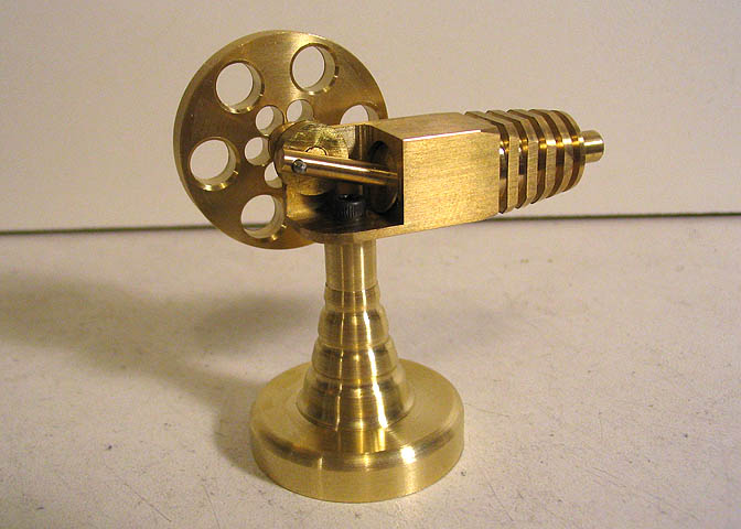
Building a rocker engine (pneumatic engine):
http://www.deansphotographica.com/machining/engines/rocker/rocker.html

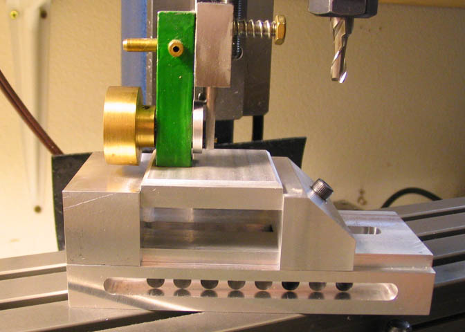
Making a screwless vice (utilizes ball bearings):

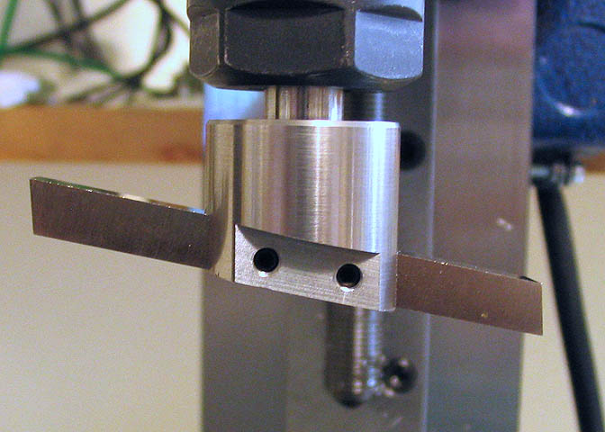
Making a flycutter (a type of bit for accurately machining the inside diameter of a hole??)