Found on Makezine.com: http://blog.makezine.com/2011/10/20/how-to-three-servos-walking-robot-video/
This robot is from a how-to on Let's Make Robots by Frits Lyneborg. It is a simple walker that has a nice design. Often walking robots can be quite complex.
There are three servo motors: two for the feet and one at the hips that shifts the weight and position of the legs. There is a four bar linkage in the "leg area" that lifts one leg up at a time. The side bars are the legs, which also hold the servos for the feet. The upper, normally horizontal bar has a high stick with the battery pack, so that when bar is slanted the weight is tipped to one side, which helps the walking movement. While standing on one foot, the foot servo rotates so that the body swings forward. The basic idea is like when you "walk" a large object, like a big board or piece of plywood, by tipping it a little on a corner and swinging the other corner forward, then repeat by alternating the corners.
The creator also uses paint mixing sticks and hot glue, which is simple and works great. He hot glues symmetrical pieces together so that any drilled holes will line up exactly. Then he cracks them apart. The microcontroller is just a simple Picaxe.
Tuesday, June 12, 2012

Alarm clock project: landing page
This is a landing page for my alarm clock project. There are three posts on this project, so I though it would be helpful to have one overview page that I can direct people to.
I have a cheap plastic alarm clock that had small buttons, specifically the alarm off button. So I wanted to replace them and mount bigger buttons (I added a big snooze button too). I used Adafruit's small and simple arcade buttons (which I've described in this informative post, in case you want to know about them for your project) and wired them to the button contacts on the inside. I took out the CD player to make room for the buttons cut holes in the top to mount them. It turned out great in the end.
First post: initial opening and beginning research
Second post: cutting
I have a cheap plastic alarm clock that had small buttons, specifically the alarm off button. So I wanted to replace them and mount bigger buttons (I added a big snooze button too). I used Adafruit's small and simple arcade buttons (which I've described in this informative post, in case you want to know about them for your project) and wired them to the button contacts on the inside. I took out the CD player to make room for the buttons cut holes in the top to mount them. It turned out great in the end.
First post: initial opening and beginning research
Second post: cutting
Thursday, May 17, 2012
Curved flexible sheet creating a flip flop, valve, or flap
I saw a classmate recognize this in class once and he was showing it to our Physics teacher. Hold a piece of paper in your hand on the side like you're grabbing a plate or the side of a tray and curve it using your fingers and thumb on either side of the paper. Then drop something on the other end of the paper. If you orient the paper concave up, the object will be caught inside the scoop shape. If you orient the paper concave down, the object will collapse the arch shape and drop past the paper onto the table.
Concave up....
 ...catches the object.
 Concave down...
 ...lets the object fall past as the paper bends. Usually the object slides down one of the sides of the arch too, so you'd have to account for that in a practical application.

This reminds me of a flip-flop, valve, or flap, such as the ones seen in sorting machines or marble machines.
You could make this with a material that is a little more stiff and predictable, like rubber or a flexible plastic. The flap could be rotated with a motor or a rotating pneumatic actuator. It could be angled so that when an object gets caught on the concave up side it slides down and away like in a channel.
However, the same actuator that rotates the flap can be used to direct objects much more simply. The two-way action could be done with a stiff, spring loaded flap that is kept from moving one way with a stopper or ledge, like a door jam, and able to freely open in the other direction. So this flap design must be uniquely beneficial for the resources of an actuator to be used up in this way.
One beneficial example I've thought of (which doesn't even require an actuator) is a door into a container that keeps objects from getting out (concave up side faces inside container), but lets objects in (concave down side faces out). This container could be vibrating or tumbling the objects inside, so a one-way opening is needed. The container might be naturally round, like a tire, so this concave flap could be built into its geometry, instead of being an abnormality like a square or circular door.
Search sorting machine on Youtube, or Lego sorting machine.
Related marble machine flip flop:
http://www.sentex.net/~mwandel/marbles/flipflop.html

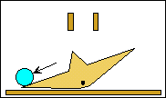
Concave up....


This reminds me of a flip-flop, valve, or flap, such as the ones seen in sorting machines or marble machines.
You could make this with a material that is a little more stiff and predictable, like rubber or a flexible plastic. The flap could be rotated with a motor or a rotating pneumatic actuator. It could be angled so that when an object gets caught on the concave up side it slides down and away like in a channel.
However, the same actuator that rotates the flap can be used to direct objects much more simply. The two-way action could be done with a stiff, spring loaded flap that is kept from moving one way with a stopper or ledge, like a door jam, and able to freely open in the other direction. So this flap design must be uniquely beneficial for the resources of an actuator to be used up in this way.
One beneficial example I've thought of (which doesn't even require an actuator) is a door into a container that keeps objects from getting out (concave up side faces inside container), but lets objects in (concave down side faces out). This container could be vibrating or tumbling the objects inside, so a one-way opening is needed. The container might be naturally round, like a tire, so this concave flap could be built into its geometry, instead of being an abnormality like a square or circular door.
Search sorting machine on Youtube, or Lego sorting machine.
Related marble machine flip flop:
http://www.sentex.net/~mwandel/marbles/flipflop.html
Metals that can be molded like plastics
From Makezine.com: http://blog.makezine.com/2012/01/13/metals-that-can-be-molded-like-plastics/

The original article is very good at describing the situation and solution to making metals that are less like hard, orderly crystals and more like grainy, moldable, "amorphous" materials like glass and plastic. The method involves cooling the metal quickly enough so that its molecules don't have enough time to settle down in an orderly configuration and must "freeze" where they are. However, this is practically impossible with pure metals since they have all the same atoms and are extremely orderly to begin with. You can't remove heat fast enough. So alloys are made where the mixture of atoms has a distribution of sizes that do not settle easily.
The first alloy was created in the lab in 1960, from three atoms of silver for each atom of silicon. However, "elaborate means were required to cool the samples fast enough, and they had to be small and thin—wires, ribbons, or foils less than 100 micrometers thick."
In the 1990s, researchers at CalTech made a better alloy with a lower "critical cooling rate."

The original article is very good at describing the situation and solution to making metals that are less like hard, orderly crystals and more like grainy, moldable, "amorphous" materials like glass and plastic. The method involves cooling the metal quickly enough so that its molecules don't have enough time to settle down in an orderly configuration and must "freeze" where they are. However, this is practically impossible with pure metals since they have all the same atoms and are extremely orderly to begin with. You can't remove heat fast enough. So alloys are made where the mixture of atoms has a distribution of sizes that do not settle easily.
The first alloy was created in the lab in 1960, from three atoms of silver for each atom of silicon. However, "elaborate means were required to cool the samples fast enough, and they had to be small and thin—wires, ribbons, or foils less than 100 micrometers thick."
In the 1990s, researchers at CalTech made a better alloy with a lower "critical cooling rate."
The first commercial amorphous metal alloy was brought to market in 2003 by CalTech spin-off Liquidmetal Technologies. Called Vitreloy 1, it’s about 40% zirconium, 20% berylium, and 10% each of titanium, copper, and nickel.Again, read the original article, it has the best information there.
Vitreloy 1 and its successors have a number of exceptional properties. They are strong, hard, and (unlike crystalline metals) they do not shrink appreciably on freezing, and thus can be injection-molded, blow-molded, and otherwise formed using the same economical processes as plastics. Designing tooling for amorphous metals requires paying attention to the critical cooling rate of the material; if some volume of the part cools too slowly, the alloy there will crystallize, shrink, and spoil it.
Ranque-Hilsch vortex tube
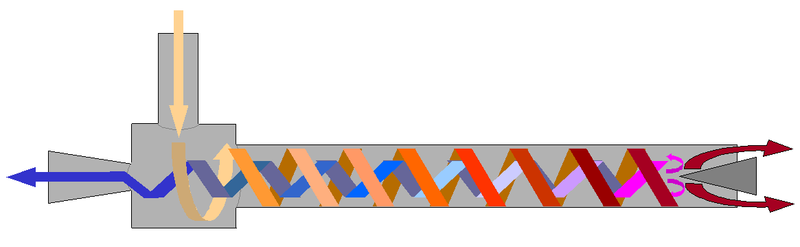
A tube that separates a neutral temperature stream of compressed air into hot and cold streams, with no moving parts. There are multiple explanations for how it works. Air is fed into the main tube by small tangential inlets, so the gas swirls. After that there are separating-effects at the ends, which have uniquely shaped openings.
This Hack-a-day post shows how to make one, by Otto Belden. Note the efficiency!
"His latest version, which you can see in the video below, takes compressed air at about 78degrees and spits out about 112degrees on the hot side and 8degrees on the cold side."

From Wikipedia:
-----------
The vortex tube, also known as the Ranque-Hilsch vortex tube, is a mechanical device that separates a compressed gasinto hot and cold streams. It has no moving parts.Pressurized gas is injected tangentially into a swirl chamber and accelerated to a high rate of rotation. Due to the conical nozzleat the end of the tube, only the outer shell of the compressed gas is allowed to escape at that end. The remainder of the gas is forced to return in an inner vortex of reduced diameter within the outer vortex.
There are different explanations for the effect and there is debate on which explanation is best or correct.
What is usually agreed upon is that the air in the tube experiences mostly "solid body rotation", which simply means the rotation rate (angular velocity) of the inner gas is the same as that of the outer gas. This is different from what most consider standardvortex behavior — where inner fluid spins at a higher rate than outer fluid. The (mostly) solid body rotation is probably due to the long time which each parcel of air remains in the vortex — allowing friction between the inner parcels and outer parcels to have a notable effect.
It is also usually agreed upon that there is a slight effect of hot air tending to "rise" toward the center, but this effect is negligible — especially if turbulence is kept to a minimum.
One simple explanation is that the outer air is under higher pressure than the inner air (because of centrifugal force). Therefore the temperature of the outer air is higher than that of the inner air.
Another explanation is that as both vortices rotate at the same angular velocity and direction, the inner vortex has lost angular momentum. The decrease of angular momentum is transferred as kinetic energy to the outer vortex, resulting in separated flows of hot and cold gas.[1]
This is somewhat analogous to a Peltier effect device, which uses electrical pressure (voltage) to move heat to one side of a dissimilar metal junction, causing the other side to grow cold.
When used to refrigerate, heat-sinking the whole vortex tube is helpful.
-----------
Robot climbs cloth by rolling along a wringle
From IEEE Automation: http://spectrum.ieee.org/automaton/robotics/home-robots/clothbot-has-no-trouble-navigating-your-pants
From the Chinese Academy of Science, called Clothbot. It has two rollers/wheels that pinch the material into a wrinkle, then roll up (or down) this winkle like on a rail. Motors twist the tail/body and the wheels to change direction.
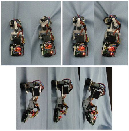
From the Chinese Academy of Science, called Clothbot. It has two rollers/wheels that pinch the material into a wrinkle, then roll up (or down) this winkle like on a rail. Motors twist the tail/body and the wheels to change direction.
Tuesday, March 13, 2012
Alarm clock project 3: installing buttons, final look
First post: initial opening and beginning research
Second post: cutting


Hope you thought that was interesting!
Second post: cutting
This is the third post.
This post is how I cut holes for and installed the buttons. There are pictures at the bottom for how the alarm clock turned out.
I used this hole-saw drill bit, which was 1'', and I needed something a little bigger than 1 1/8". 1 1/4" would be too big.

Clamping the lid. I put a wooden spacer underneath that was flush to the lid. This way the underside of the cut would be cleaner.

Pictures after drilling.


Here you can barely see the pencil outline of the desired hole. I have to sand away that much.

Poor man's sander. After sanding by hand a bit, the sandpaper taped around the hole saw would fit. This method worked pretty well. First I sanded it by hand, then spun it with a drill. I was careful not to let the hole saw slip or cut me while I held the lid.

Sanded holes.

Test fit, it worked well.

Test fit.


Mounting the button circuit board.

These mounting posts originally held the CD player circuit board too, so I had to substitute these extra silver washers to make the screw tighten.

Here's how I soldered the buttons. I just connected them to the leads of the existing buttons so that they would still operate.

I left enough slack in the wires so that one could open the lid and see inside and so that they could bend easily to a good closed position.

Here's soldering the wires from the backup battery (for when the power goes out). This is the first time I used heat shrink tubing; I heated it with a lighter, which worked well enough.

As you can see from the above picture, I forgot to put the wire through the hole in the circuit board before soldering back together. So I had to cut it, put it through the hole, and solder it again (it wouldn't fit around). :P

Closed lid.

How the wires reach under.

Finished alarm clock.

What's visible when you open the lid.

Hope you thought that was interesting!
Alarm clock project 2: cutting
First post: initial opening and beginning research
This is the second post.
Third post: installing buttons, final look
So I completely finished this project a little over a month or so. It's taken a crazy long time for me to post on it since I first started (Nov '11). Sorry about that for anybody who reads this and notices the discontinuity. I'll finish it up today.
I wanted to install bigger snooze and alarm off buttons on my alarm clock for ease of use. Read the first post for more information.
This post is about how I cut the unnecessary plastic away with a hacksaw. (cutting the holes for the buttons comes next.


This is the second post.
Third post: installing buttons, final look
So I completely finished this project a little over a month or so. It's taken a crazy long time for me to post on it since I first started (Nov '11). Sorry about that for anybody who reads this and notices the discontinuity. I'll finish it up today.
I wanted to install bigger snooze and alarm off buttons on my alarm clock for ease of use. Read the first post for more information.
This post is about how I cut the unnecessary plastic away with a hacksaw. (cutting the holes for the buttons comes next.
First I figured out where the holes should go so that I know what is in the way. With the data sheet and a caliper I figured out the correct size of the hole. These buttons have clever clasps/latches/"wings" that push out on the hole to keep the button in place. These flex like a spring and adapt to a range of hole sizes, so I didn't need to be super precise. I drew the hole size on some graph paper with a compass so I could check the placement and draw around it on the alarm clock. The hole in the middle of the paper is for lining it up with the center lines I drew on the alarm clock (using the lines in the graph paper).

I'm using the darker circles closer to the center, as opposed to the lighter ones near them.

Underneath the cover, inside the clock. The dark, straight lines is where I'll be cutting material away. After establishing the placement of the buttons on the top, I measured up and over from the edges to be able to transpose the positions on the underside.

Another view.

The underside for reference.

I cut the plastic with a hacksaw blade. I protected my hand with some duct tape on one end. You can see my crude hilt for slip protection. :) (The alarm clock top has been removed.)

I basically took some diagonal cuts that were increasingly shallow. I sanded and filed the edges when I got close enough.


Half way through I realized I could test the buttons on the center hole for the CD player spinner. It worked ok, but was a little loose. When it slipped into the hole I stabbed myself on that sharp corner near the laser symbol. :(

One side finished. The rounded corner was first cut a couple of times with the hacksaw blade, then sanded a bunch.

The other side.


Finished. I sanded all the edges to make them smooth, including the edge on the CD circle that already existed. It was painted silver and it contrasted with the true black plastic color from the cuts nearby.

Subscribe to:
Posts (Atom)